Blog
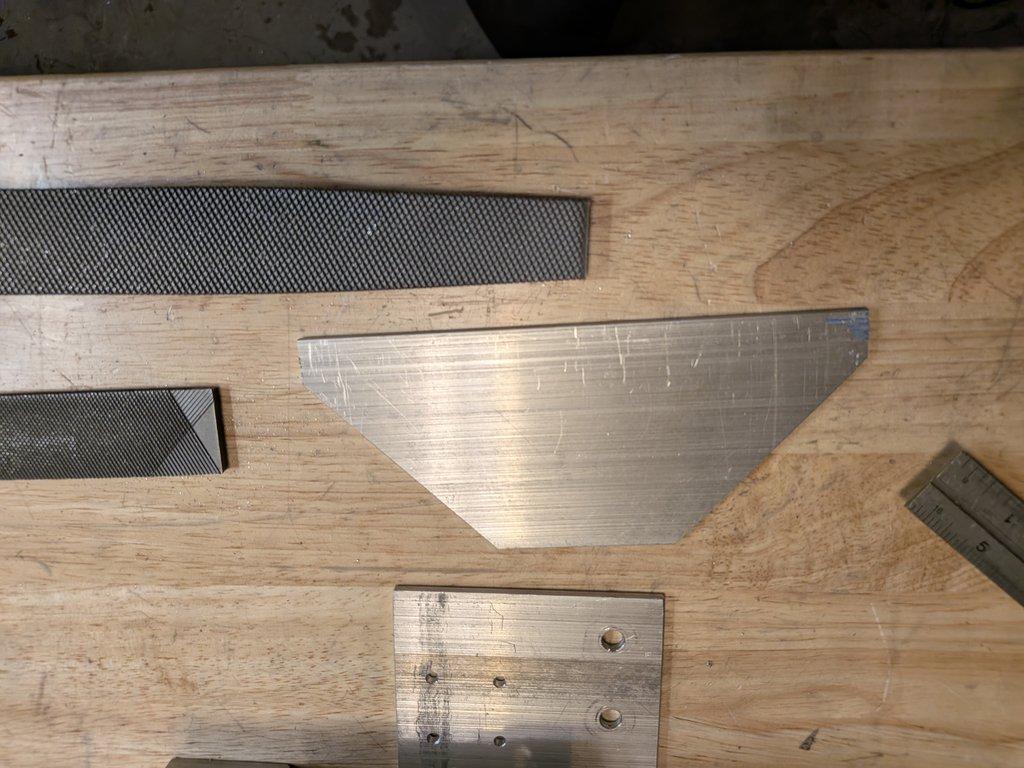
Tilt Elbow Cut & Head Mockup
This set of images shows cutting the gussets for the tilt elbow, and then bringing the pan and tilt arms together for a quick mockup.
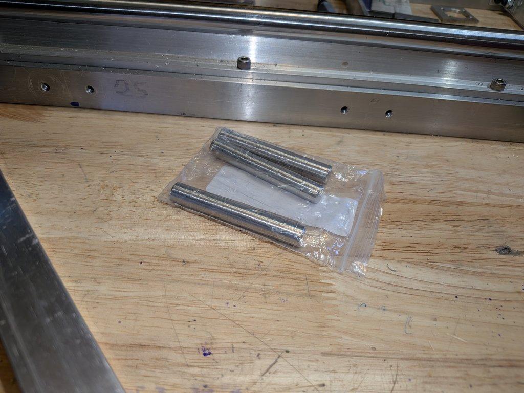
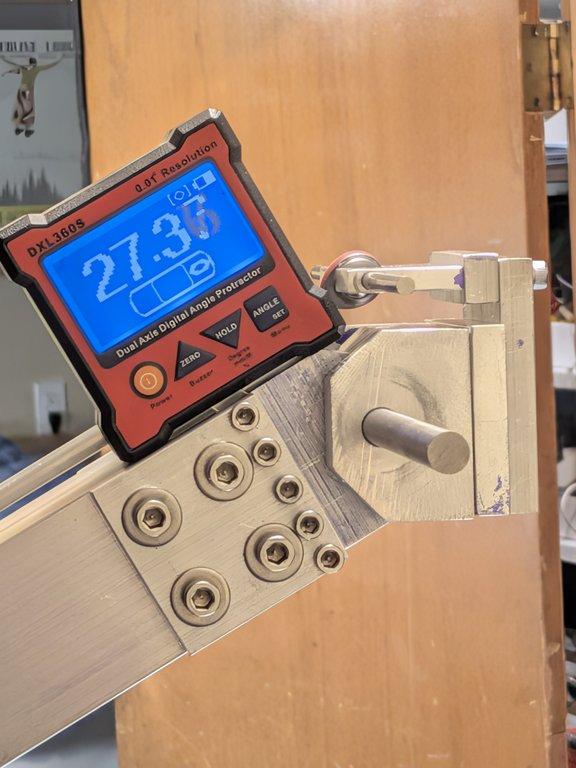
Boom Head Hinge Pin
This set is a quick one—showing the 10mm pin used for the hinge at the end of the boom.
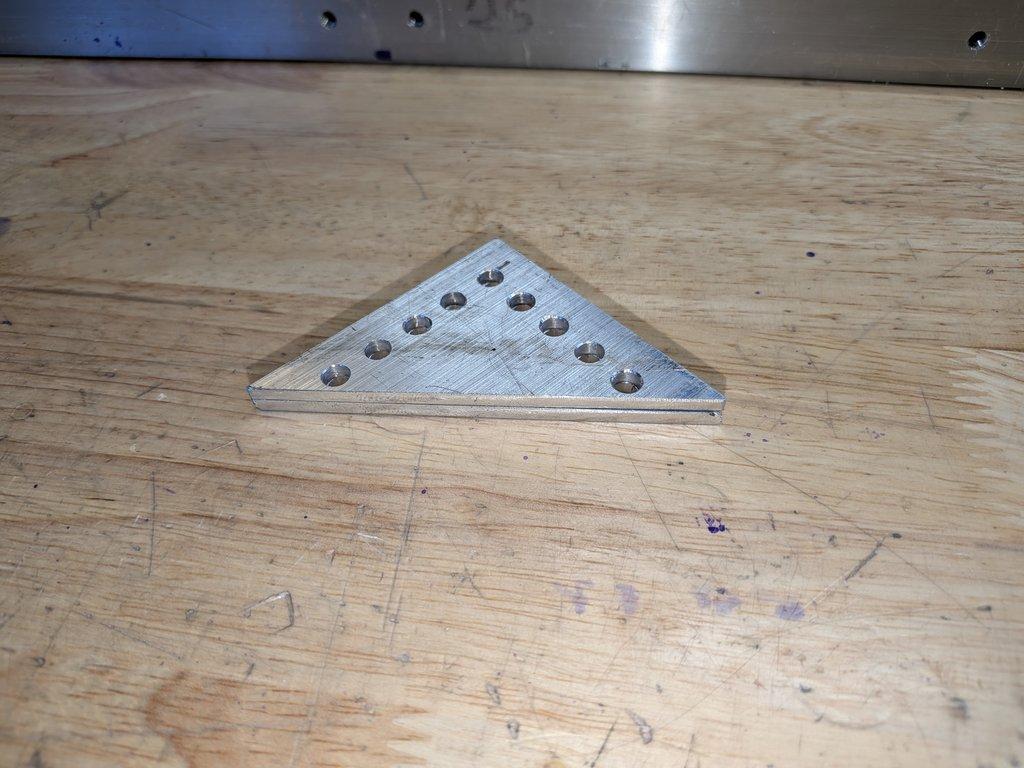
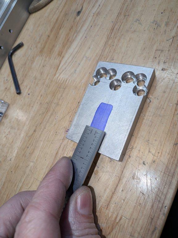
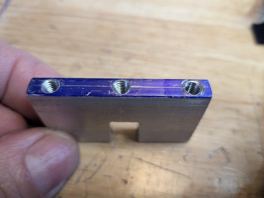
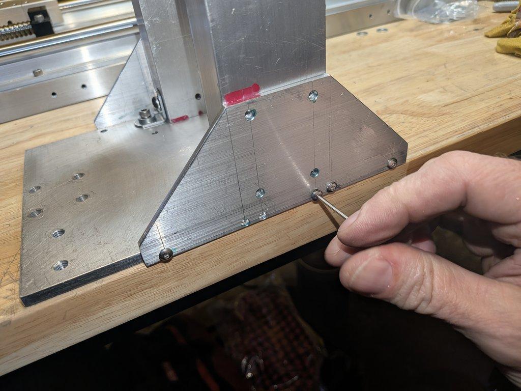
Gussets & Hole Alignment
Following on the previous post about improving layout accuracy, this set shows the fabrication of the two gussets and the hole patterns that tie them into the tube structure.
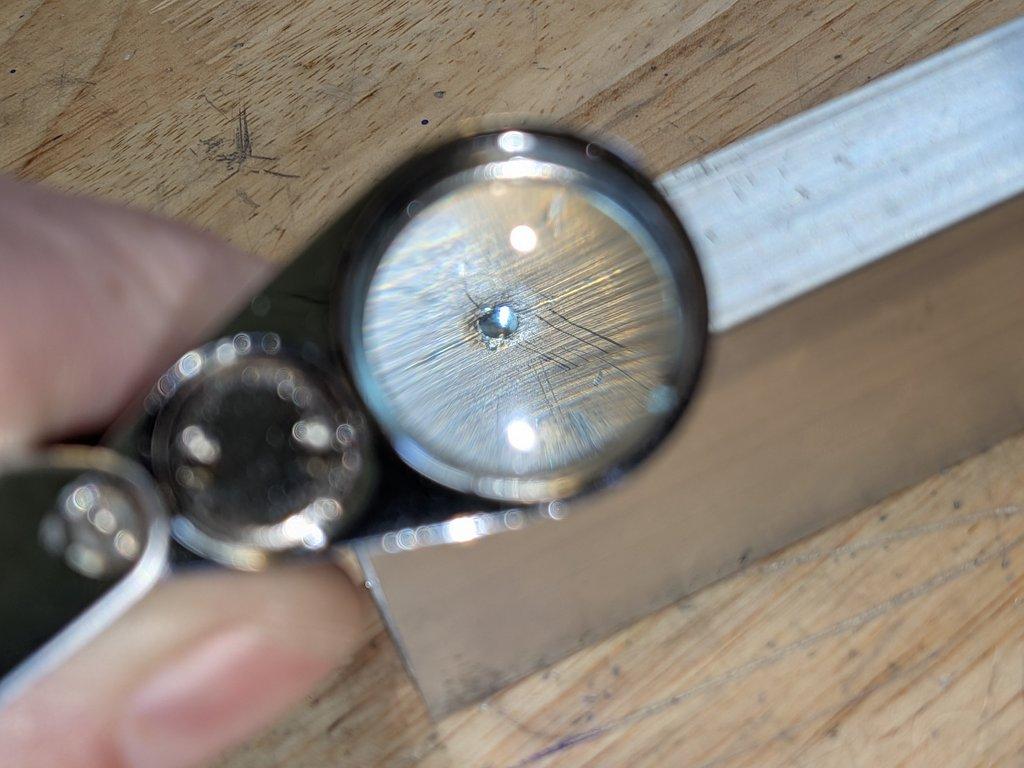
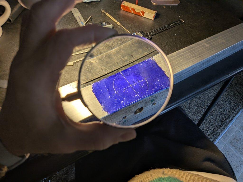
Magnification for Accurate Center Punching
This is a quick one, but a useful detail.
Pan Axis Shaft & Bearing Fitment
This set of images shows drilling the hole for the 10mm shaft, which will serve as a shoulder bolt for the pan rotation axis.
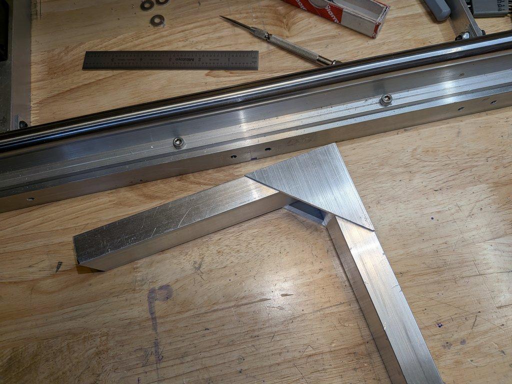
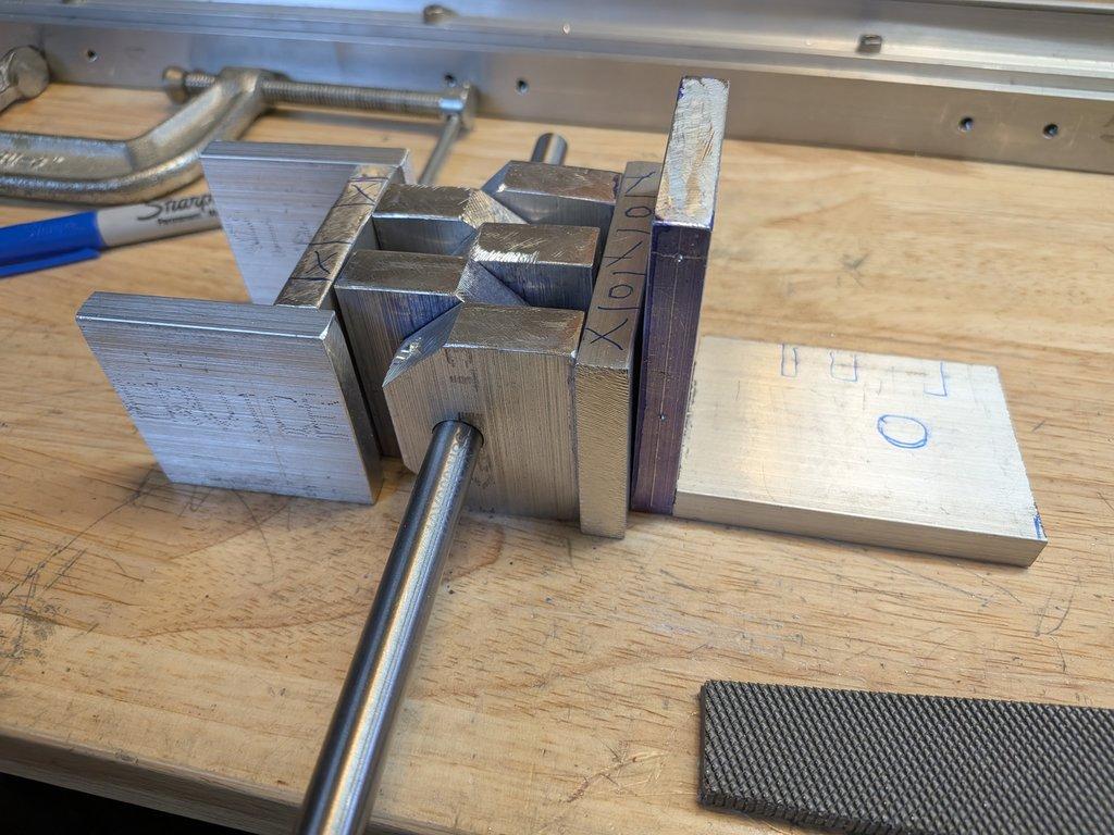
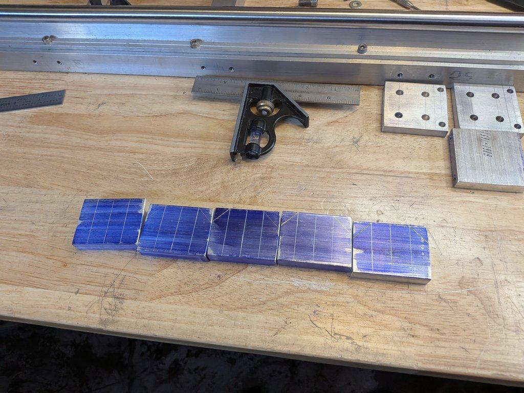
Head Elbows: Tube Cutting & Gusset Fitment
This set of images shows the fabrication of the smaller rectangular tube sections that make up the pan-to-tilt connection in the camera head.
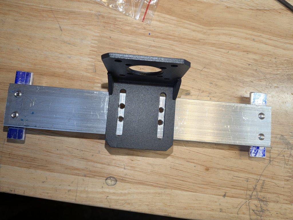
Swing Motor Mount Plate & Belt Tension
This stage shows the final fabrication of the motor mount plate for the swing axis, along with the first fitment of the belt system.
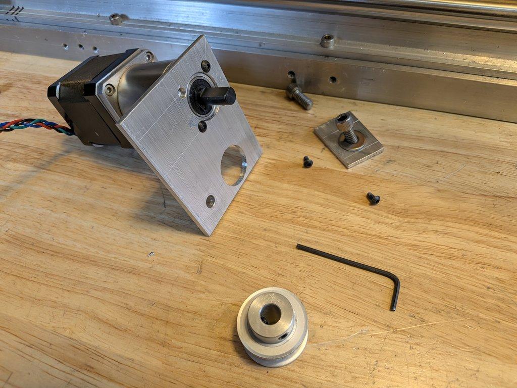
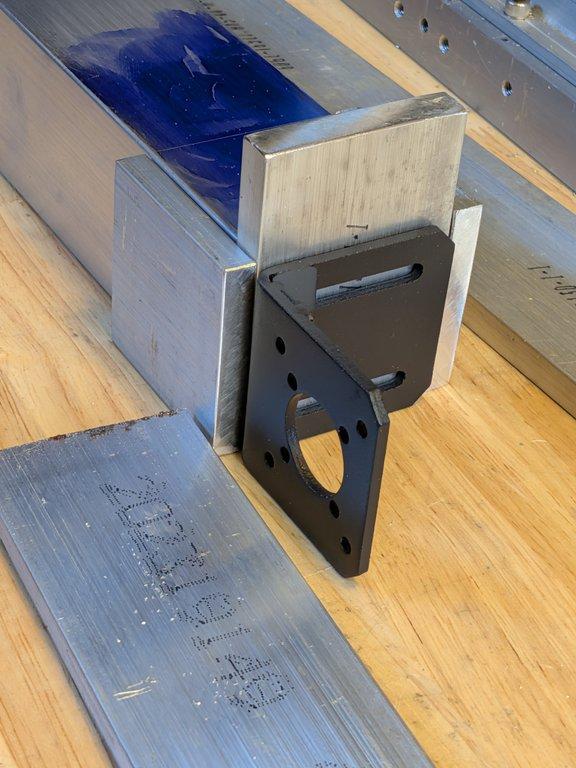
Track Drive Motor Bracket Fitment
This set of images shows the motor mounting bracket being fitted to the motor mount cross brace for the track drive.
Diving Board Layout & Fitment
This stage goes back into layout and fitment for what I’ve been calling the “diving board”—the extension off the hinge block that carries the head assembly.
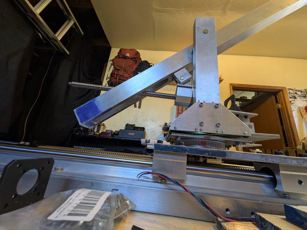
First Motion & Range of Motion Test
This set of images coincides with the first time the boom arm was moved under motion control.
Adapter Plate, Layout Fluid & Linkage Details
This stage shows the installation of the adapter plate that connects the hinge block (on the camera head side) to the vertical linkage that ties into the yoke and the upper parallelogram link.
Parallelogram Top Link & Yoke Bracket
This stage focuses on a small yoke-style bracket that mounts an eyelet at the top end of the jib arm system.
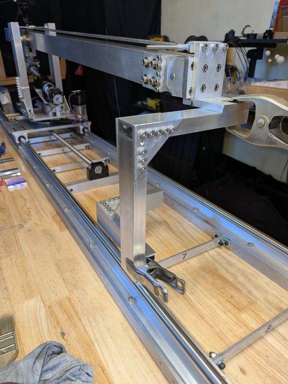
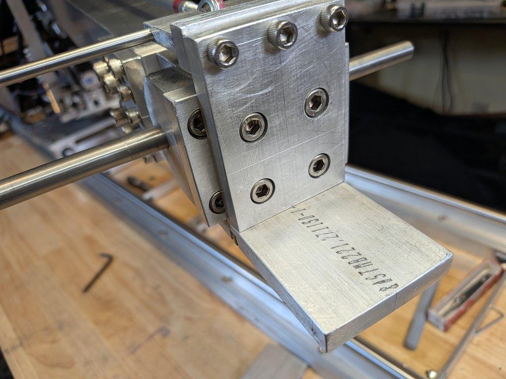
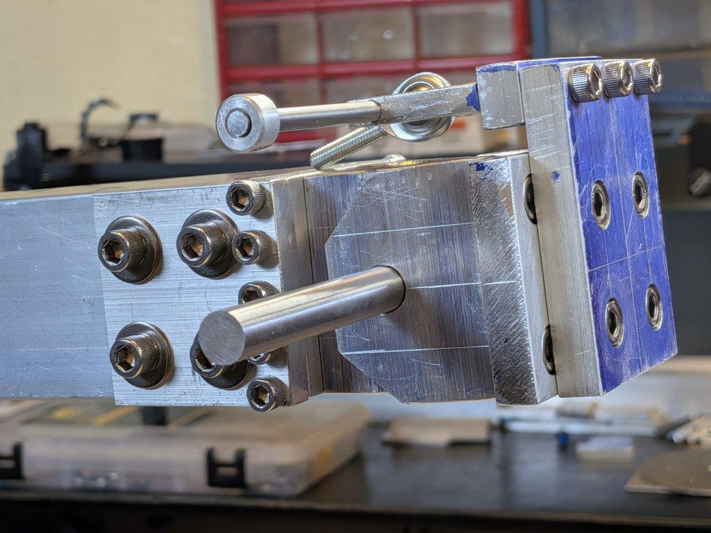
Boom End Mockup: Hinge, Mount Blocks & Pan Drive
This stage is a full mockup of the boom end assembly—bringing together the hinge, the hinge mount blocks, and the pan drive transmission block (what I’ve been thinking of as the “diving board” at the
Boom End Hinge Fabrication
This stage focuses on building the hinge at the end of the boom arm—the point that will support the pan/tilt/roll head, or more simply, the camera head.
Boom End Plates & Drive Slot Fabrication
This stage moves from mockup into fabrication, focusing on the end plates for the boom arm and refining the slot that allows the boom drive to pass through the boom.
Boom Arm End Mockup
This stage focuses on mocking up the end of the main boom arm, using the square tube to begin defining how the next layer of mechanics will attach.
Boom Arm Modification & Ball Screw Clearance
This stage focuses on modifying the boom arm to better integrate with the drive system
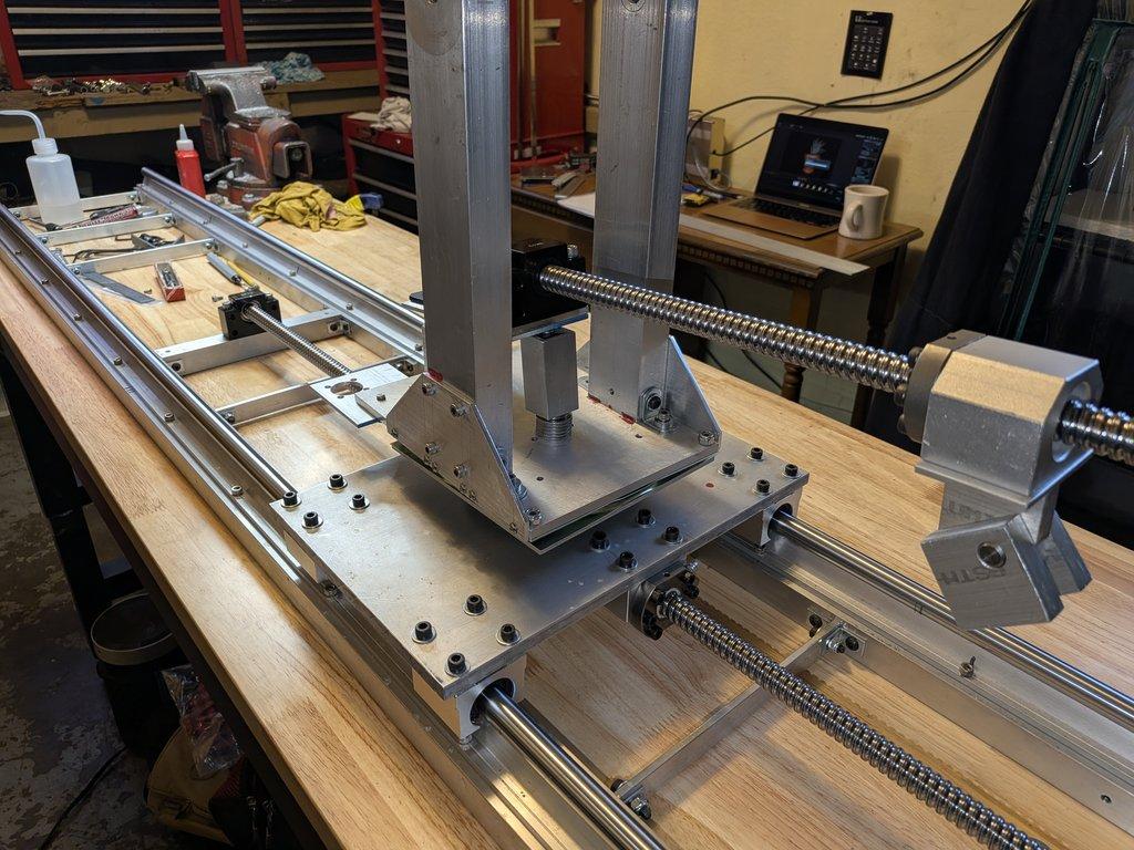
Base Assembly & Boom Drive Fitment
This stage brings together several major components: the base plate, uprights with gussets installed, and the boom drive motor.
Gussets Installed & Swing Base Assembly
This stage shows the gussets installed on the uprights, along with a clearer look at the swing rotation stage and the base plate with uprights attached.
Repositioning Uprights & Adding Gussets
This stage involves reworking the placement of the uprights on the base plate and adding gussets to support them